不喜歡 AutoLisp 的 Polar 函數?
P-De 可以利用 【基準點】、【角度】、【距離】、【標記】,四個參數來取得相對點位。
這個角度非弧角是 Degrees
;;;************************************************************************
(defun P-De (BasePoint Degrees Dist Mark / ang return-Pt)
(setq ang (* pi (/ Degrees 180.0)))
(setq NPt (polar BasePoint ang Dist))
(if (/= Mark "")
(command "text" "J" "MC" NPt "3" "0" Mark "")
)
(setq return-Pt NPt)
)
NPXY 可以利用 【基準點】、【X軸】、【Y軸】、【標記】,四個參數來取得相對點位。
;;;************************************************************************
(defun NPXY
(BasePoint Xaxis Yaxis Mark / Ptx PtY ang1 ang2 return-Pt)
(setq ang1 (* 0 pi))
(setq ang2 (* 0.5 pi))
(setq Ptx (polar BasePoint ang1 Xaxis))
(setq PtY (polar Ptx ang2 Yaxis))
(if (/= Mark "")
(command "text" "J" "MC" PtY "3" "0" Mark "")
)
(setq return-Pt PtY) ;回傳值
)
其中第四個參數【標記】是除錯用的 。
參考下圖,我打算利用 NPXY 這個改寫的新函數來繪製 RH 並且變成通用程式。
先做一個測試用基本框架,由於RH 型鋼決定於五個參數 H B T1 T2 R 先給定值做測試用如下:
(defun c:pp (/ H B T1 T2 R PIns)
(setq PIns (getpoint
(strcat "請點選基準點 : ")
)
)
(setq
H 150
B 75
T1 5
T2 7
R 8
)
(RH-Draw H B T1 T2 R PIns)
)
接著在AutoCAD 中繪製該RH 所有其他點位接參考 P1,再利用 PIns 決定P1位置,為了不用輸入負值,以左下為 P1
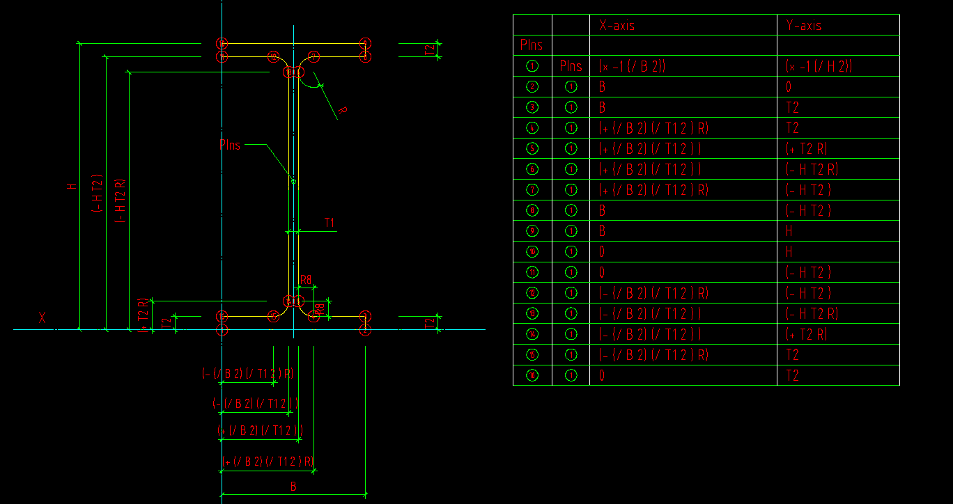
對這個圖形來說X軸只有 0 、(- (/ B 2) (/ T1 2 ) R)、(- (/ B 2) (/ T1 2 ) )、(+ (/ B 2) (/ T1 2 ) )、(+ (/ B 2) (/ T1 2 ) R)、B 幾種 ,其中0 的有 P1 、P16、P10、P11,就一次寫在 X 軸,(- (/ B 2) (/ T1 2 ) R) 為P12、P15 也是這樣類推 ,很輕鬆的就全部相對點位都出來了。
接著我們要撰寫主結構中的 (RH-Draw H B T1 T2 R PIns) 圖形繪製程式
(defun RH-Draw (H B T1 T2 R PIns / P1 P2 P3 P4
P5 P6 P7 P8 P9 P10 P11 P12 P13 P14 P15
P16
)
(setq
P1 (NPXY PIns (* -1 (/ B 2)) (* -1 (/ H 2)) "")
P2 (NPXY P1 B 0 "")
P3 (NPXY P1 B T2 "")
P4 (NPXY P1 (+ (/ B 2) (/ T1 2) R) T2 "")
P5 (NPXY P1 (+ (/ B 2) (/ T1 2)) (+ T2 R) "")
P6 (NPXY P1 (+ (/ B 2) (/ T1 2)) (- H T2 R) "")
P7 (NPXY P1 (+ (/ B 2) (/ T1 2) R) (- H T2) "")
P8 (NPXY P1 B (- H T2) "")
P9 (NPXY P1 B H "")
P10 (NPXY P1 0 H "")
P11 (NPXY P1 0 (- H T2) "")
P12 (NPXY P1 (- (/ B 2) (/ T1 2) R) (- H T2) "")
P13 (NPXY P1 (- (/ B 2) (/ T1 2)) (- H T2 R) "")
P14 (NPXY P1 (- (/ B 2) (/ T1 2)) (+ T2 R) "")
P15 (NPXY P1 (- (/ B 2) R) T2 "")
P16 (NPXY P1 0 T2 "")
)
(command "Pline" P1 P2 P3 P4 "Arc" P5
"Line" P6 "Arc" P7 "Line" P8 P9 P10
P11 P12 "Arc" P13 "Line" P14 "Arc" P15
"Line" P16 P1 ""
)
)
由於要在中軸作插入點因此P1 必須參考自 PIns 所以原本的
P1 (NPXY PIns 0 0 "")
改成
P1 (NPXY PIns 0 0 "")
改成
P1 (NPXY PIns (* -1 (/ B 2)) (* -1 (/ H 2)) "")
完整的測試碼如下:
(defun c:pp (/ H B T1 T2 R PIns)
  (setq PIns (getpoint
        (strcat "請點選基準點 : ")
      )
  )

  (setq
    H  150
    B  75
    T1 5
    T2 7
    R  8
  )

  (RH-Draw H B T1 T2 R PIns)
)

;;;************************************************************************

(defun RH-Draw (H    B   T1   T2   R  PIns /    P1 P2   P3   P4
  P5   P6   P7   P8   P9  P10  P11  P12 P13  P14  P15
  P16
        )
  (setq
    P1 (NPXY PIns (* -1 (/ B 2)) (* -1 (/ H 2)) "")
    P2 (NPXY P1 B 0 "")
    P3 (NPXY P1 B T2 "")
    P4 (NPXY P1 (+ (/ B 2) (/ T1 2) R) T2 "")
    P5 (NPXY P1 (+ (/ B 2) (/ T1 2)) (+ T2 R) "")
    P6 (NPXY P1 (+ (/ B 2) (/ T1 2)) (- H T2 R) "")
    P7 (NPXY P1 (+ (/ B 2) (/ T1 2) R) (- H T2) "")
    P8 (NPXY P1 B (- H T2) "")
    P9 (NPXY P1 B H "")
    P10 (NPXY P1 0 H "")
    P11 (NPXY P1 0 (- H T2) "")
    P12 (NPXY P1 (- (/ B 2) (/ T1 2) R) (- H T2) "")
    P13 (NPXY P1 (- (/ B 2) (/ T1 2)) (- H T2 R) "")
    P14 (NPXY P1 (- (/ B 2) (/ T1 2)) (+ T2 R) "")
    P15 (NPXY P1 (- (/ B 2) R) T2 "")
    P16 (NPXY P1 0 T2 "")
  )


  (command "Pline"  P1 P2     P3     P4     "Arc"  P5
    "Line" P6  "Arc" P7     "Line" P8     P9     P10
    P11   P12  "Arc" P13    "Line" P14    "Arc"  P15
    "Line" P16  P1 ""
   )
)


;;;************************************************************************
(defun P-De (BasePoint Degrees Dist Mark / ang return-Pt)
  (setq ang (* pi (/ Degrees 180.0))) ; 轉換成弧角
  (setq NPt (polar BasePoint ang Dist)) ;取得新點位
  (if (/= Mark "")   ;除錯檢查用可以在點位給定標籤
    (command "text" "J" "MC" NPt "3" "0" Mark "")
  )
  (setq return-Pt NPt)   ;回傳值
)


;;;************************************************************************
(defun NPXY
     (BasePoint Xaxis Yaxis Mark / Ptx PtY ang1 ang2 return-Pt)
  (setq ang1 (* 0 pi))
  (setq ang2 (* 0.5 pi))
  (setq Ptx (polar BasePoint ang1 Xaxis)) ; X 方向暫存點
  (setq PtY (polar Ptx ang2 Yaxis)) ; Y 方向取得新點位
  (if (/= Mark "")   ;除錯檢查用可以在點位給定標籤
    (command "text" "J" "MC" PtY "3" "0" Mark "")
  )
  (setq return-Pt PtY)   ;回傳值
)
如果你在第四個參數【標記】加入字串如:
P1 (NPXY PIns (* -1 (/ B 2)) (* -1 (/ H 2)) "P1")
P2 (NPXY P1 B 0 "P2") ..... 中略
P9 (NPXY P1 B H "P9")
P10 (NPXY P1 0 H "P10")
圖形便會出現標籤,如前面的說明這是為除錯用的

你可以再操控 H B T1 T2 R PIns 四個參數就可以繪製所有 RH 剖面了。
回想以前寫過的程式片段...
(setq p1 (polar insPt (* 0.5 pi) (/ H 2.0)))
(setq p1 (polar p1 pi (/ B 2)))
(setq x (/ (- B (+ t1 R R)) 2))
(setq y (- H (+ t2 t2 R R)))
(setq P2 (polar p1 (* 0 pi) B))
(setq P3 (polar p2 (* 1.5 pi) t2))
(setq P16 (polar p1 (* 1.5 pi) t2))
(setq P4 (polar p3 (* 1 pi) x))
(setq P15 (polar p16 (* 0 pi) x))
(setq c1 (polar p4 (* 1.5 pi) R))
(setq c2 (polar p15 (* 1.5 pi) R))
(setq P5 (polar c1 (* 1 pi) R))
(setq P14 (polar c2 (* 0 pi) R))
(setq P6 (polar p5 (* 1.5 pi) y))
(setq P13 (polar p14 (* 1.5 pi) y))
(setq c3 (polar p6 (* 0 pi) R))
(setq c4 (polar p13 (* 1 pi) R))
(setq P12 (polar c4 (* 1.5 pi) R))
.........
天阿自己要改寫或除錯都很暈 ,而且用了很多參考點位。
標籤: AutoLisp
張貼者:Wildkid 於
8月 29, 2014
![]()


3 個意見:
我自己是用dtr 和rtd 2個自定函數做角度和弳度間轉換 ,比較直觀..用pi 我會稿混.!!
(polar pt (dtr 45) dist)
2014年9月6日 星期六 上午8:59:00 [PDT]
我也是
大部分程式都需要角度,其實 NPXY 會有絕對座標問題。
我另外一個副程式是P-De (如本文中),這個才是常用的,我在後面加了一個除錯標籤字串參數
2014年9月6日 星期六 上午10:22:00 [PDT]
除錯標籤 好用.
2014年9月7日 星期日 上午8:51:00 [PDT]
張貼留言
訂閱 張貼留言 [Atom]
<< 首頁